Installation & Wiring
1. Powering Up the KIN D 2.0
The KIN D 2.0 will operate on a DC or AC power supply (not provided) within the range of 12 to 24 volts. If the KIN D 2.0 and attached device are required to operate in the event of a power outage, a Battery Backed-Up Power Supply is recommended. If the attached device requires more than 0.5 AMPS of current to operate, a heavy duty power supply is required. The KIN D 2.0 uses an embedded relay with a 2.0 amp rating.
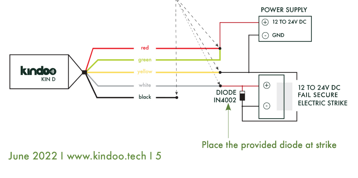
This is the maximum current that can be switched reliably when connected to a NON-Inductive load up to 30 VDC. Electric strikes and magnetic locks are considered Inductive Loads. For inductive loads operating on DC, it is important to have the provided diode attached at the locking device to remove the CEMF pulse that is generated when switching an inductive load (see the wiring example below). For inductive loads operating on AC, a MOV must be used (not provided).
An external relay should be used on larger voltage and current requirements.
Use the provided 5 wire caps for wire connections. ALWAYS terminate any unused KIN D 2.0 wire with a wire cap.
2. KIN D 2.0 Placement
- Place the KIN D 2.0 in a plastic enclosure or within the wall or door frame, in a dry place with normal ambient temperatures.
To avoid any attenuation and for proper operation, DO NOT place the KIN D 2.0 behind electrical equipment such as a card reader, screens, etc.
DO NOT place the KIN D 2.0 behind metallic obstacles or behind UV coated glass or reflective glass.
3. Testing the Operational Range
Once the KIN D 2.0 is placed, always test its operational range. When issuing a command, the KINDOO application will inform you if the KIN D 2.0 signal is weak and will not emit the command.
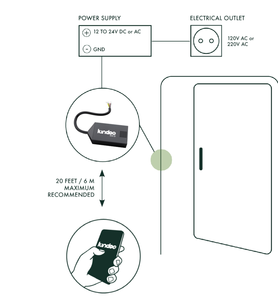
Always verify that the range within which the KINDOO application allows you to issue the command is an acceptable operational range for your installation. If not, change the KIN D 2.0 placement in a way that reduces obstacles between the KIN D 2.0 and the phone of the users.
For installations where the KIN D 2.0 is hidden, you may use the provided Kindoo Sticker and double-sided tape to affix the sticker in a visible location at the same level as the KIN D 2.0. The sticker simply helps users know where the KIN D 2.0 is located and does not serve any other function.
4. Wire Color Coding
| Wire | Function |
|---|---|
| Red | Common (C) — typically 12V to 24V DC or AC |
| White | Normally Open (NO) |
| Black | Normally Closed (NC) |
| Green & Yellow | Provide power to the KIN D and should be connected to a 12V to 24V DC or AC power supply |
5. Wiring Example: DC Fail Secure Electric Strike Requiring Less Than 2 AMPS
- Use the 5 provided wire caps to connect wires.
- Note that green and yellow wires can be switched.
- The electric strike current draw should be less than 2 amps.
- The KIN D 2.0, diode, and wire caps are included. The power supply and electric strike are not provided.
- Power Supply 1 should NOT be connected to any component or load other than the ones in the circuit below.
- Most importantly, terminate any unused wire with a wire cap as well.
- The diode should be connected at the strike level, and not on the wires in between the strike and the KIN D.
6. Wiring the KIN D to an Exit Device
- Make sure to have a direct run of wires between the power supply and the exit device.
- Do NOT wire any relay, KIN D, or any other access control unit between the power supply and the exit device.
- Use a dedicated second power supply, 12V to 24V DC rated 1 AMP, to power the KIN D. Do not wire any other component to that dedicated power supply.
For more wiring examples specific to common exit devices, see the Wiring Diagrams page.
7. Riser Diagram
8. Setup
Use the KINDOO mobile application to set up KIN D 2.0 devices.